Tuesday, 19 May 2015

cisco 1841 router configuration


As I’ve done the “getting started” with an ASA 5505, seeing as the CCNA security not only covers the ASA units but also securing routers, I thought I’d best do a quick getting start tutorial for the Cisco 1841. (seeing as I have a number of these routers in my home lab).
What I’m going to cover in this tutorial are much the same as the ASA:
  • Setup Cisco 1841 with outside access (internet access)
  • Setup Cisco 1841 as a DHCP server for your inside network
  • Setup Cisco 1841 with access to the SDM
Right then, lets being…..
For this example, Ethernet 0/0 will be used as the outside connection (192.168.5.69), ethernet 0/1 will be our inside LAN connection (192.168.10.0/24).
Once again I’ll be using teraterm to configure the device via the serial connection.
Let’s skip past the usual alerts for a new device (e.g the automatic setup wizard), and lets run some of the usual housekeeping commands
Now let’s configure up both the WAN and LAN interfaces on the router like so:
Finally let’s put in a default route to route all traffic out to our ISP router (192.168.5.254). Try to ping 8.8.8.8 (don’t worry if the first times out as its ARP’ing remember), but to be sure try to ping again and you should get no time outs
Now we have some outside access, let’s continue with setting up the 1841 to act as a DHCP for our inside LAN (as currently our clients will be sitting with APIPA addresses – 169.254…..)
As you will see it’s slightly different to the ASA (in terms of commands) but it’s all there, you just need to find it. If in doubt ? mark it (as you will see in the below output I used the ? to find out the various options I can use when configuring the scope). Then finally at the bottom you will see I’ve excluded the first 9 addresses.
Next come’s our good old friend NAT, so let’s configure both interfaces with NAT inside and NAT outside.
I’ve now created a VERY simple access-list as you can see it just allows everything
Finally I’ve entered in our NAT statement to say anything sourced from ACL 100 is permitted and the outside interface (Ethernet 0/0) is the port where the PAT will take place.
Now if you open up a webpage you should see plenty of NAT translations and you should have the ability to browse the internet, magic!
Now we’ve got the basic access, I’m going to move on to configuring access to the SDM. If you’ve never used SDM it’s the original GUI. Think of it as the first version of ASDM (as you see with the ASA firewall). It’s basic yet you can still do a lot via the GUI, I prefer not to use this at all, and stick to command line but once again each too their own.
So let’s get started and configure a username/password/privilege level.
Once done, let now enable the HTTP secure server, and select the authentication used for HTTPS connections
And that’s it!
Browse to https://192.168.10.254, login using your username and password.
wait for the SDM to load and then that’s it, you’ve now got GUI access to your Router.
You’re now good to go!

How to Configurate the Cisco 1841 detailedly?

This is a very common question that most of the nonspecialists may ask when configuring the newly purchased Cisco Router 1841. Basically one FA will be the Internet so you need something like:
int fa0/0
ip address 210.215.117.213 255.255.255.252
ip nat outside
int fa0/1
ip address 210.115.117.81 255.255.255.248
ip nat inside
ip route 0.0.0.0 0.0.0.0 210.215.117.214
Cisco Router 1841
In addition, you will have to use the following commands :
access-list 1 permit  210.215.117.80 0.0.0.7
ip nat inside source list 1 interface fa0/0 overload
Now, let’s share the configuration details step by step.
1. After startup,the following message will appear on the configuration screen:
Would you like to enter the initial configuration dialog? [yes/no]:
Type “yes” and press the “Enter” key.
2. Type “yes” in response to the following prompt:
Would you like to enter basic management setup? [yes/no]:
3. Create and enter a router hostname following the prompt. Follow your network’s standard naming protocols if applicable. If your naming protocol requires that you use the router’s physical location, such as “3rd Floor Server Room,” to identify the router, follow it.
4. Create and type in the following passwords when prompted. First, create an enable encrypted secret password which has been scrambled so that it cannot be read. Next, create an unencrypted enable password, which you can view when viewing the router’s configuration file; in case you will view the router’s configuration file if you are trouble-shooting problems with the router. Finally, create a virtual terminal password, which secures access to the router through non-console ports which are connections to the router that you make remotely, as opposed to those that you make when you are physically standing close to the router.Cisco 1841 rear panel
5. Type “Yes” to configure SNMP Network Management following the prompt, or “No” if you do not need it for your network. Enter the associated public community string if you entered “Yes”. The system will display a summary of the interfaces available for you to use.
6. Enter an interface that the router will use to connect to the management network from the displayed summary of available interfaces.
7. Type “Yes” to enable FastEthernet support, which allows the router to transmit data through the network at a fast rate of 100 megabits per second. Type in “Yes” to enable RJ-45 connectors, which are the plugs on the router that look like oversize telephone plugs, and into which you insert network cables. Type in “Yes” to enable duplex-mode operations, so that data can travel both to and from the router simultaneously, instead of traveling in only one direction at a time. Enter an IP address if you want to set an address manually. When you have finished, the router will display the new configuration and prompt you to save it.
8. Type “2″ at the prompt to save the new configuration to “nvram”, and exit.

Friday, 15 May 2015

How To Boost Your Home Wi-Fi Signal (Part 2)

In part two of his Home Wi-Fi performance series, Sandro Villinger provides more tips to speeding up your home network.
Is your Wi-Fi network still going slow even after ourfirst bunch of tips? Are you even experiencing occasional drop-outs and disconnects?
In part two of our Wi-Fi optimization series, we’ll show you how to boost the signal strength of your Wi-Fi network even further. If you missed part one, go check it out!

Set up a wireless repeater

If your property has thick walls or is so large that your router cannot simply broadcast a good signal from one end to the other, it’s probably wise to get a wireless repeater:
Repeater

These look very similar to a router and pick up your Wi-Fi signal and rebroadcast it with renewed strength. The repeater connects to your wireless router as a regular client, getting an IP address over DHCP much like your regular laptop or PC.
  • Position: I suggest following our first tip of part 1 of this guide to determine weak spots of your wireless router. Place the repeater close to this spot but make sure that it’s able to pick up a good signal (80% or more) from your main router. Otherwise it won’t be able to repeat a good quality signal.
  • Hardware: When choosing a repeater, don’t be confused by the different names – some companies tend to name their repeaters as ‘Range extenders’ while others call them ‘Wi-Fi expanders’ or something similar. They are all the same. Simply make sure to pick one that rebroadcasts your 802.11n or ac signal and make sure that it’s compatible.
  • Set up: Every manufacturer has different setup procedures but in general all that is needed is your network name and password.

Tip: Check out these resources for a general overview or this huge guide on how to use your router as a universal wireless repeater.

Optimize the Wi-Fi settings

There are many complicated settings on your router which can help you optimize the signal in your home. Unfortunately, every manufacturer offers different options under a different name, so we’ll just give a handful of hints that explain where to look and what to look for. Also there are some settings that you should check to see if they are set at their default values:
  • 5 Ghz Wireless Mode: If your router and adapter uses it, I’d recommend setting up a 5 Ghz Wi-Fi network instead of the regular 2.4 Ghz. Devices that support this mode are known as ‘Dual-band’.
Since most Wi-Fi routers communicate at a frequency of 2.4 Ghz, using the less common 5 Ghz mode might give you a better throughput.
 5GHz settings
To enable a 5 GHz connection, go to your router configuration page (normally shown on the device) and find your wireless settings. If you can see an option for  a 5 GHz connection, enable it!

  • RTS Threshold: RTS stands for ‘Request to send’ and is send by the client to the access point – it essentially asks for permission to send the next data packet. The lower the threshold, the more stable your Wi-Fi network, since it essentially asks more often when sending packages. However, if you don’t have problems with your Wi-Fi you should make sure that the RTS Threshold is set to the maximum allowed:
RTS Threshold
To do this, go to your router configuration and try to find the ‘RTS Threshold value’ in the wireless settings and set it to 2347.  Lower this value only if you are experiencing problems with your network (drop outs etc).
  • Fragmentation Threshold: This value is used to set the maximum size of packet a client can send. Smaller packets improve reliability, but they will decrease performance. Unless you’re facing problems with an unreliable network, reducing the fragmentation threshold is not recommended. Make sure it is set to the default settings (usually 2346).
  • Enable Multimedia/Gaming settings: Some wireless adapters can either be configured either for regular use or for gaming/multimedia. If you’re streaming video or playing games, enabling this will make sure that network packets for these are prioritised! In other words: If you’re watching a video file over your network, the video will get most of the traffic.
Advanced Settings

Benchmark and diagnose your Wi-Fi

This tip is not an optimization technique per se but it’s a great way to determine if our tips so far have had a positive effect on your network. Free ‘QCheck’ is a great tool that will show you the response time, throughput and streaming performance of your wireless setup. You can easily get it from this website after you filled out a short form.
QCheck
Enter your IP address under ‘Endpoint 1’ and another IP address in your network under ‘Endpoint 2’ to test the speed. This will give you important information when trying to optimize your Wi-Fi with our tips.

Replace your antenna!

Some router manufacturers sell external antennae that are much stronger than the router’s built-in antenna. If your signal is weak in places (and all our other tips have failed), then you’ll need to check if your manufacturer sells either omnidirectional or directional antennae:
  • Omnidirectional: Sends out a signal into all directions. By default, most built-in antennas are omnidirectional. If an omnidirectional antenna is your choice, make sure to look out for a longer one with ‘high gain’.
Antenna

  • Directional antenna: This kind of antenna sends a good wireless signal in a certain direction instead of spreading it in all directions, improving the performance in the target area. It’s like pointing a flashlight in a certain direction instead of using your regular ceiling lamps!
To connect a new antenna, you’ll usually use the SMA connector or MMCX. For more on wireless antennae, I can highly recommend the ‘Do-It-Yourself Wireless Antenna Update’ website by BinaryWolf. You’ll find great how-to guides and hardware recommendations that’ll help you pick the best antenna and the right setup!

That’s it! Using these tips and tricks will definitely improve your Wi-Fi performance and experience –  if you’ve got another tip that you use to boost your wireless network let us know!

How To Boost Your Home Wi-Fi Signal (Part 1)

Do you regularly lose connectivity to your Wi-Fi network at home? Are network speeds so low that it takes forever to even copy a simple picture or music file across your PCs – let alone stream video? In this two-part series, we are covering the most important lessons and tips for boosting wireless (WLAN) throughput across your home network. Ready? Let’s dive in!

Figure out the best possible router position

Have you wondered why your wireless signal is strong in some rooms and incredibly weak in others? It’s not only a matter of distance between your wireless router and your PCs or laptops. It’s also a matter of what objects (walls, doors, furniture, electrical equipment/outlets) interfere with a good signal.
In many scenarios, you will be able to boost wifi strength significantly by just repositioning either your router or the connected PCs slightly.
Now, the “Trial and error” method works eventually, but is a waste of time. To get the best possible location you need to create a visualization of network coverage across your home. Heatmapper, a free software for Windows, will do just that:

Click here to download Heatmapper (100 MByte). Note: A registration is required to download this free tool.
After installation, the program asks you if you’ve got a map of your map of your floor – no worries, if you don’t, you can create this heatmap based on a grid. Simply walk around your apartment or house with a laptop in your hand running Heatmapper. As you walk (slowly!), use the left-click button frequently as you walk. Walk through all the areas of your home left-clicking as much as you can.
When you’re done, right click and HeatMapper will create a map of your home, showing you where the Wi-Fi signal is stronger or weaker. Here’s how my map at home looks like:
The green area in the middle is also the center of my apartment – a good location for the router! However, in the bedroom (upper part of the screen) I only get „ok“ wireless strength because the router is blocked by three walls.
By looking at the heatmap, I quickly knew where to position the router in order to get a better Wi-Fi signal!
General advice: Make sure not to position the router directly on the floor or next to thick walls. Ideally, the best position is in the center (probably the corridor) of your apartment with no or minimal objects blocking the signal!

Use the latest drivers and firmware

It’s rare to find firmware for a router or driver for a network adapter that works perfectly right out of the gate. Most „V1“ drivers and firmwares of network equipment I have used were bad and came with all sorts of problems: slow connections, drop outs, missing features and other quirks. The first thing I always do when I get a new network device is: look for updates!

For example, when I bought my Linksys WUSB600N adapter it didn’t work (at all!) under the 64-bit-version of Windows 7. I actually bought the device and couldn’t use it for a couple of weeks until the manufacturer delivered an updated driver that worked under the x64 architecture.
Upgrading the firmware of your router has become somewhat easy over the past couple of years: Simply open up the firmware configuration page in your browser (see below) and find the „Firmware Upgrade“ page.
Here you will find direct links to drivers for some popular router manufacturers:
These links will you to the most recent Wi-Fi drivers available. Your wireless adaptor is not on the list? You haven’t found anything using popular search engines? Hit the comment section and provide us with the detailed specs of the Wi-Fi adaptor as shown in your device-manager.

Upgrade your Wi-Fi hardware

If you’re using the 802.11g (or even b/a) wireless standard, more bandwidth-related tasks such as video streaming, launching remote applications or file copy operations will be painfully slow. All three network standards provide a relatively low maximum bandwidth:
Theoretical speed
802.11 (1997)2 MBps
802.11a (1999)54 MBps (short range, high cost – mostly in business use)
802.11b (1999)11 MBps (slower, but higher range than a)
802.11g (2002)54 MBps (long signal range)
802.11n (2006)300 MBps (through multiple channels and frequencies)
802.11ac (2012)1 GBps (through multiple channels and frequencies)
As you can see, 802.11ac is the way to go these days. Over the next couple of months, it’ll replace the older 802.11a/b/g networks, and offers much improved speed, coverage and reliability. In general, 802.11ac is at least twice as fast than its predessor “n” while promising theoretical speeds of up to 1000 Mbp/s.
If you’re suffering from a low network bandwidth, be sure to pick a router and Wi-Fi adapters that supports at least the 802.11n specification. If you bought a PC or laptop within the last couple of years, it’ll (very likely) have a 802.11ac wireless adapter. To go check, simply fire up Device-Manager…
…or take a look at your hardware specification sheet, for example:
If your adapter does not support 802.11n or ac but your router does, it’ll obviously use the lower N, G, B or even A modes. So make sure that all parts of your wireless chain are “n” compatible!
When shopping for a new network adapter or a router that supports 802.11ac, you should take the following three tips into consideration.

Pick a dedicated USB adapter:

Even if your laptop or desktop has a built-in 802.11ac adapter that is connected to a full-fledged 802.11n router, you might want to look into getting a dedicated (external) USB wireless adapter. Sounds ridiculous, but in my experience many external Wi-Fi adapters perform much better than built-in devices.
When I first got my Linksys WRT610N router, I got quite mixed results and only an average of 100-170 Mbps when the theoretical limit of this beast is around 300 Mbps. So I drank the cool-aid and ordered the adapter that, according to the manufacturer Linksys, “works best with” my router – the WUSB600N USB wireless adapter! And what a difference that made: Signal strength did not change, but the speed went up significantly. Here’s a screenshot of my laptop that’s using both the built-in Wi-fi chip as well as the external USB adapter to connect to the router:
The maximum speed meter went up from 130 Mbps to 300 Mbps. Of course, that is the peak value, but only with this little addition was I able to stream full-definition 1080p video across my apartment with no stuttering or delay whatsoever.

Stay in the family: Besides using external dedicated Wi-Fi devices, I’d also recommend to pick a router and the adapter from the same company. Now, that doesn’t mean that a Linksys router wouldn’t work with a Broadcom or D-Link network adapter, but it’s also my experience that you get the best-possible performance if you „stay in the family“. Now I know that this is what the manufacturer wants but in this case I’d go with it.
Use an external antenna for your router. You can significantly boost your Wi-Fi connection by replacing the antenna or add another external antenna. This guide as well as this one help you figure things out.

Change the Wi-Fi channel

All modern routers are capable of communicating to your PC or laptop on several different channels. However, if your neighbours Wi-Fi equipment is communicating on the same channel, your network speeds and reliability might suffer. Windows offers a built-in solution that lets you see on what channels all your surrounding Wi-Fi networks conmunicate. This is how it works:
Step 1 – Launch the command line. To do that, click on the Start orb, go to „All ProgramsAccessories“ and click on „Command Prompt“.
Step 2 – Type in the following command: netsh wlan show all.

Step 3 – You’ll see a large list of all wireless networks in your area.
Scroll through the list and watch out for the entry that says „Channel“. Out of those 7 networks, 4 are using channel 6 to send data, two use channel 5 and one is using channel 13.

This is why I should probably choose either a lower channel or a channel between 6 and 13.
Try changing the channel on the routers configuration page.
To open the page, you’ll usually enter it’s IP adress into your browser (check the manual to see which address you need to type in), for example http://192.168.1.1, and enter the user name and password you specified at setup – or the default credentials if you never specified it (which is potentially dangerous)!
Find your wireless channel settings. On my router, that’s under the “Wireless” tab right in the “Basic Wireless Settings” category:
Pick the channel that is not (or barely) used in your area. In my example, I choose channel 10. Reconnect all your devices and see if you’ve got better speed or if you’re reliability issues are fixed!
That was part 1 – look out for part 2 that’ll show you even more in-depth tricks to improve your wireless network speed!

Friday, 1 May 2015

Data Communication & Computer Network

Data communications refers to the transmission of this digital data between two or more computers and a computer network or data network is a telecommunications network that allows computers to exchange data. The physical connection between networked computing devices is established using either cable media or wireless media. The best-known computer network is the Internet.
This tutorial should teach you basics of Data Communication and Computer Network (DCN) and will also take you through various advance concepts related to Data Communication and Computer Network.

Audience

This tutorial has been prepared for the computer science graduates to help them understand the basic to advanced concepts related to Data Communication and Computer Networking. After completing this tutorial you will find yourself at a moderate level of expertise in Data Communication and Computer Networking from where you can take yourself to next levels.

DCN - Transport Layer Introduction

Next Layer in OSI Model is recognized as Transport Layer (Layer-4). All modules and procedures pertaining to transportation of data or data stream are categorized into this layer. As all other layers, this layer communicates with its peer Transport layer of the remote host.
Transport layer offers peer-to-peer and end-to-end connection between two processes on remote hosts. Transport layer takes data from upper layer (i.e. Application layer) and then breaks it into smaller size segments, numbers each byte, and hands over to lower layer (Network Layer) for delivery.

Functions

  • This Layer is the first one which breaks the information data, supplied by Application layer in to smaller units called segments. It numbers every byte in the segment and maintains their accounting.
  • This layer ensures that data must be received in the same sequence in which it was sent.
  • This layer provides end-to-end delivery of data between hosts which may or may not belong to the same subnet.
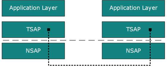
  • All server processes intend to communicate over the network are equipped with well-known Transport Service Access Points (TSAPs) also known as port numbers.

End-to-End Communication

A process on one host identifies its peer host on remote network by means of TSAPs, also known as Port numbers. TSAPs are very well defined and a process which is trying to communicate with its peer knows this in advance.
TSAP
For example, when a DHCP client wants to communicate with remote DHCP server, it always requests on port number 67. When a DNS client wants to communicate with remote DNS server, it always requests on port number 53 (UDP).
The two main Transport layer protocols are:
  • Transmission Control Protocol
    It provides reliable communication between two hosts.
  • User Datagram Protocol
    It provides unreliable communication between two hosts.

DCN - Network Layer Protocols

Every computer in a network has an IP address by which it can be uniquely identified and addressed. An IP address is Layer-3 (Network Layer) logical address. This address may change every time a computer restarts. A computer can have one IP at one instance of time and another IP at some different time.

Address Resolution Protocol(ARP)

While communicating, a host needs Layer-2 (MAC) address of the destination machine which belongs to the same broadcast domain or network. A MAC address is physically burnt into the Network Interface Card (NIC) of a machine and it never changes.
On the other hand, IP address on the public domain is rarely changed. If the NIC is changed in case of some fault, the MAC address also changes. This way, for Layer-2 communication to take place, a mapping between the two is required.
ARP Mechanism
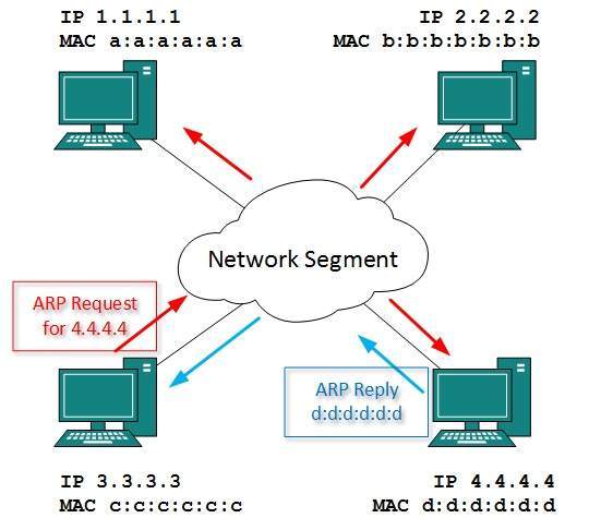
To know the MAC address of remote host on a broadcast domain, a computer wishing to initiate communication sends out an ARP broadcast message asking, “Who has this IP address?” Because it is a broadcast, all hosts on the network segment (broadcast domain) receive this packet and process it. ARP packet contains the IP address of destination host, the sending host wishes to talk to. When a host receives an ARP packet destined to it, it replies back with its own MAC address.
Once the host gets destination MAC address, it can communicate with remote host using Layer-2 link protocol. This MAC to IP mapping is saved into ARP cache of both sending and receiving hosts. Next time, if they require to communicate, they can directly refer to their respective ARP cache.
Reverse ARP is a mechanism where host knows the MAC address of remote host but requires to know IP address to communicate.

Internet Control Message Protocol (ICMP)

ICMP is network diagnostic and error reporting protocol. ICMP belongs to IP protocol suite and uses IP as carrier protocol. After constructing ICMP packet, it is encapsulated in IP packet. Because IP itself is a best-effort non-reliable protocol, so is ICMP.
Any feedback about network is sent back to the originating host. If some error in the network occurs, it is reported by means of ICMP. ICMP contains dozens of diagnostic and error reporting messages.
ICMP-echo and ICMP-echo-reply are the most commonly used ICMP messages to check the reachability of end-to-end hosts. When a host receives an ICMP-echo request, it is bound to send back an ICMP-echo-reply. If there is any problem in the transit network, the ICMP will report that problem.

Internet Protocol Version 4 (IPv4)

IPv4 is 32-bit addressing scheme used as TCP/IP host addressing mechanism. IP addressing enables every host on the TCP/IP network to be uniquely identifiable.
IPv4 provides hierarchical addressing scheme which enables it to divide the network into sub-networks, each with well-defined number of hosts. IP addresses are divided into many categories:
  • Class A  - it uses first octet for network addresses and last three octets for host addressing
  • Class B  - it uses first two octets for network addresses and last two for host addressing
  • Class C  - it uses first three octets for network addresses and last one for host addressing
  • Class D  - it provides flat IP addressing scheme in contrast to hierarchical structure for above three.
  • Class E  - It is used as experimental.
IPv4 also has well-defined address spaces to be used as private addresses (not routable on internet), and public addresses (provided by ISPs and are routable on internet).
Though IP is not reliable one; it provides ‘Best-Effort-Delivery’ mechanism.

Internet Protocol Version 6 (IPv6)

Exhaustion of IPv4 addresses gave birth to a next generation Internet Protocol version 6. IPv6 addresses its nodes with 128-bit wide address providing plenty of address space for future to be used on entire planet or beyond.
IPv6 has introduced Anycast addressing but has removed the concept of broadcasting. IPv6 enables devices to self-acquire an IPv6 address and communicate within that subnet. This auto-configuration removes the dependability of Dynamic Host Configuration Protocol (DHCP) servers. This way, even if the DHCP server on that subnet is down, the hosts can communicate with each other.
IPv6 provides new feature of IPv6 mobility. Mobile IPv6 equipped machines can roam around without the need of changing their IP addresses.
IPv6 is still in transition phase and is expected to replace IPv4 completely in coming years. At present, there are few networks which are running on IPv6. There are some transition mechanisms available for IPv6 enabled networks to speak and roam around different networks easily on IPv4. These are:
  • Dual stack implementation
  • Tunneling
  • NAT-PT

DCN - Internetworking

n real world scenario, networks under same administration are generally scattered geographically. There may exist requirement of connecting two different networks of same kind as well as of different kinds. Routing between two networks is called internetworking.
Networks can be considered different based on various parameters such as, Protocol, topology, Layer-2 network and addressing scheme.
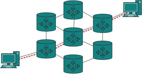
In internetworking, routers have knowledge of each other’s address and addresses beyond them. They can be statically configured go on different network or they can learn by using internetworking routing protocol.
Routing
Routing protocols which are used within an organization or administration are called Interior Gateway Protocols or IGP. RIP, OSPF are examples of IGP. Routing between different organizations or administrations may have Exterior Gateway Protocol, and there is only one EGP i.e. Border Gateway Protocol.

Tunneling

If they are two geographically separate networks, which want to communicate with each other, they may deploy a dedicated line between or they have to pass their data through intermediate networks.
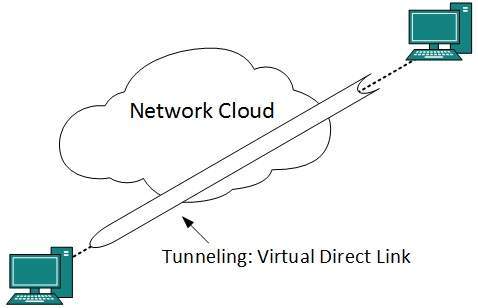
Tunneling is a mechanism by which two or more same networks communicate with each other, by passing intermediate networking complexities. Tunneling is configured at both ends.
Tunneling
When the data enters from one end of Tunnel, it is tagged. This tagged data is then routed inside the intermediate or transit network to reach the other end of Tunnel. When data exists the Tunnel its tag is removed and delivered to the other part of the network.
Both ends seem as if they are directly connected and tagging makes data travel through transit network without any modifications.

Packet Fragmentation

Most Ethernet segments have their maximum transmission unit (MTU) fixed to 1500 bytes. A data packet can have more or less packet length depending upon the application. Devices in the transit path also have their hardware and software capabilities which tell what amount of data that device can handle and what size of packet it can process.
If the data packet size is less than or equal to the size of packet the transit network can handle, it is processed neutrally. If the packet is larger, it is broken into smaller pieces and then forwarded. This is called packet fragmentation. Each fragment contains the same destination and source address and routed through transit path easily. At the receiving end it is assembled again.
If a packet with DF (don’t fragment) bit set to 1 comes to a router which can not handle the packet because of its length, the packet is dropped.
When a packet is received by a router has its MF (more fragments) bit set to 1, the router then knows that it is a fragmented packet and parts of the original packet is on the way.
If packet is fragmented too small, the overhead is increases. If the packet is fragmented too large, intermediate router may not be able to process it and it might get dropped